A Design of Semi Circular Intake Supporting Structure 1 Bellmounth Opening Transition Size of Opening Slope Angle of center line of HRT with horizontal Co-eff of Contraction. For mechanically cleaned racks the.

Trash Racks Bar Screens Cambridge Engineered Solutions
In addition the openings of a trash rack should be about half the diameter of the spillway outlet pipe.

. Trash Rack Design Trash racks are designed so that the average flow velocity through the trash racks does not exceed 25 feet per second for the full range of anticipated flow conditions. Figure 1 is a diagram of a typical trash rack. Trash rack cleaners which are used in water.
Fixed Screen Inclined Position Inclination of bar screen θ. A -area of the transverse section of water intake in the plane of the trashrack and without the trashrack A8 -area of the elements of the trashrack perpendicular to flow Cv -drag coefficient of the trashrack ca 0 -drag coefficient of the elements of the trashrack ck - effective lift coefficient CL -lift coefficient. Download view trash rack structural design as pdf for free.
Calculated pipe rack width 650585410325260475590 3295 mm Step 5. Up to 10 cash back 1. Design Calculation of Trash Rake.
Design standards assists in the development and improvement of Reclamation facilities in a way that protects the publics health safety and welfare. Storage Tank Design Calculations. This will assure large debris that could plug the.
Manually cleaned bar screens Manually cleaned bar screens have a 254 to 508 centimeter 10 to 20 inches clear. Spreadsheet models were prepared for the design and calculations of the concrete volumes and the weight of the trashrack steel structure with various assumptions. Design condition Type.
5 Sets Spek-Tek Bab 1452 hal. Add 20 future expansion to calculated pipe rack width Pipe rack width after adding future expansion calculated width 20 future expansion 3295659 3954 4000 mm. In total some 20 different intake structures were analysed and up to 60 cases.
The trash bars run from top to bottom and are supported by lateral bars or beams which carry the loads into each side of the rack. Thickness of vertical bar t 0012m width of vertical bar d 0075m clear spacing between vertical bar b 004m clear spacing between horizontal bar h 04m length of fluid body at upstream of the trashrack 2d length of fluid body at downstream of the. During operation of trash racks the realization of the design difference of levels on them and the presence of nonzero angles of attack lead to the occurrence of considerable transverse forces acting on the bars which must be taken into account by a static calculation.
Corrected the minimum debris size prevented by the trash rack per RAI 519-8687 Q1 This document was prepared for the design certification. Article reports about a design automation system for. Design calculation of trash rake.
Important dimensions used for the modelling of a trashrack are. Alternatively the following Kirschmer formula can also be used. Its free to sign up and bid on jobs.
1 in 9900 001 rad 06. Sections 21 and 22. Deformation of the bars in the plane of the rack can occur as.
Design Of Trash Rack. Search for jobs related to Trash rack design calculations or hire on the worlds largest freelancing marketplace with 20m jobs. The trash bars run from top to bottom and are supported by lateral bars or beams which carry the loads into each side of the rack.
This enabled effective output of the main cost factors when the design parameters were altered. H r 4 2 3 ssin 2 tv K bg α where h. Deformation of the bars in the plane of the rack can occur as a large span.
The trash racks must be installed in slanting positions except for guided racks where these can be kept in a vertical position. The basis for the system is a knowledge-. Hs where p total pressure per one meter kgfm ρ specific weight of water 1000 kgm3 h design differential head 3 m s bar pitch 006 m 60 mm p 1000 x 3 x 006 p 180 kgfm p 18 kgfcm 22 bending moment of each bar flat bar fb 120 x 10 corrosion allowance 2mm t 12 cm h 12 cm.
Storage Tank Design Calculations. Based engineering system which. The minimum clear spacing of.
R net area through the rack bars gross area of the racks and supports V velocity of flow through trash rack computed on gross area and g acceleration due to gravity. Recognizes needs of all stakeholders. K trash rack loss coefficient 145 045 R R2.
Slope provided 15 Degrees As per IS11388 1995 - Clause -5 CC spacing of bars provided Depth of bars provided Thickness of bars 100 mm 60 mm 12 mm As per IS11388 1995 - Clause -851 So opening size Height of Trash Rack Total width provided 88 2 328 656. Design Calculations for Irrigation Project Trash Rack Design. For manual cleaning of the racks the slope should be 1 vertical to 13 or 12 horizontal.
75 0 Quantity.

Head Loss Coefficient In Trash Rack Drawn Based On Penche 2004 Download Scientific Diagram

Pdf Design Calculation Of Trash Rake Stephanus Rahendra Academia Edu

Trash Racks Bar Screens Cambridge Engineered Solutions
2
2
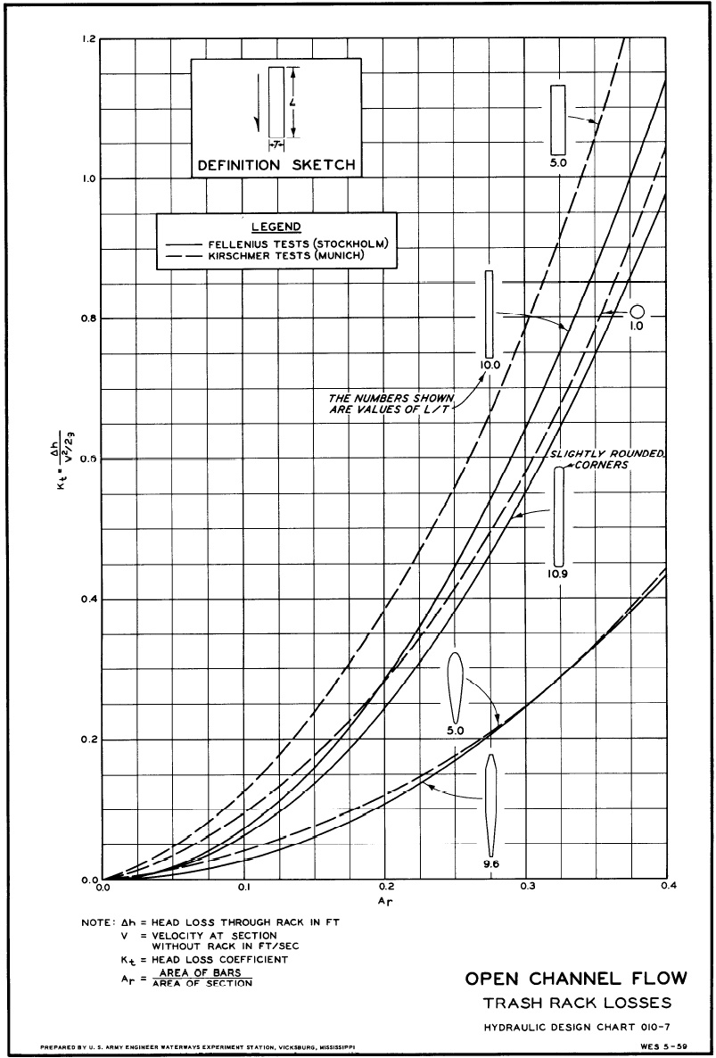
Trash Rack Losses Open Channel Flow Sheet 010 7 Ezcivil 2017 01 30 Hydraulic Design Criteria Sheet 010 7 Open Channel Flow Trash Rack Losses 1 The Energy Loss Of Flow Through Trash Racks Depends Upon The Shape

Representation Of The Angled Trashrack In The Channel A And Details Download Scientific Diagram

Typical Trashrack Structure Download Scientific Diagram
0 comments
Post a Comment